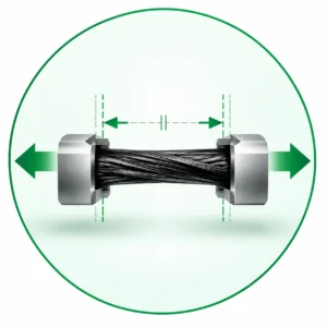
Tensile Stress
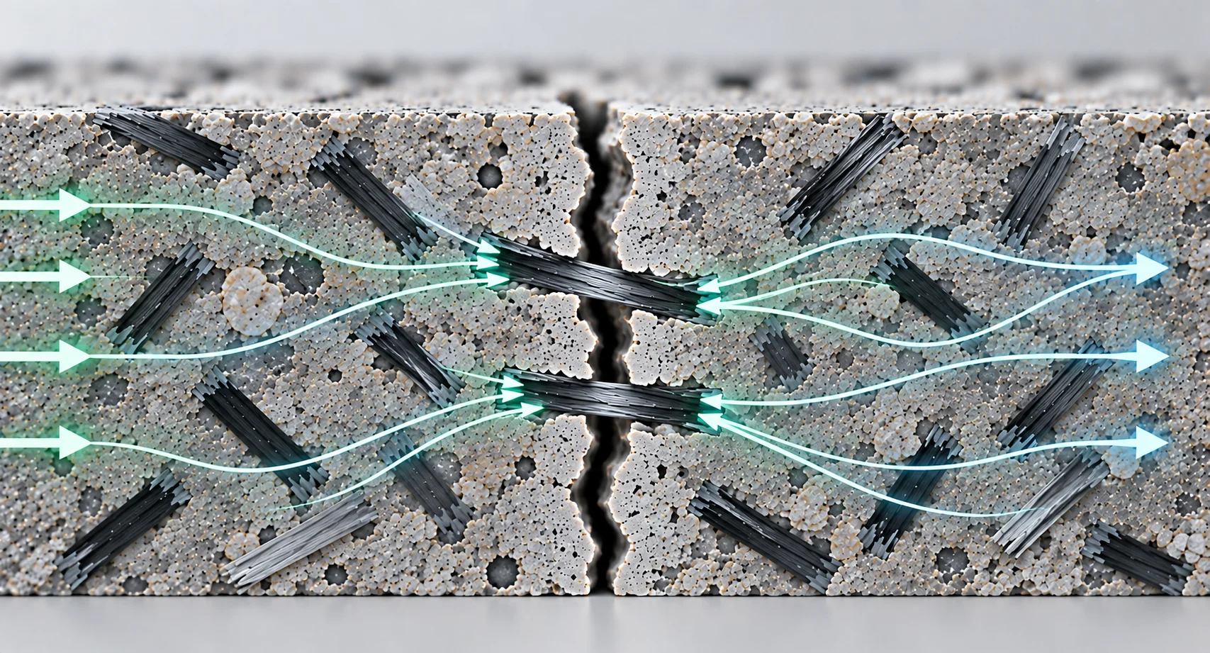
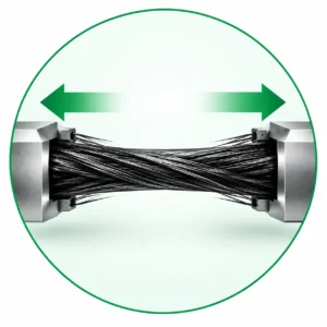
High-strength Carbon Fiber can participate in tensile load transfer within the matrix, providing distributed reinforcement where tensile stresses must be effectively managed.
High-Strength, High-Modulus Fiber for Advanced Reinforcement
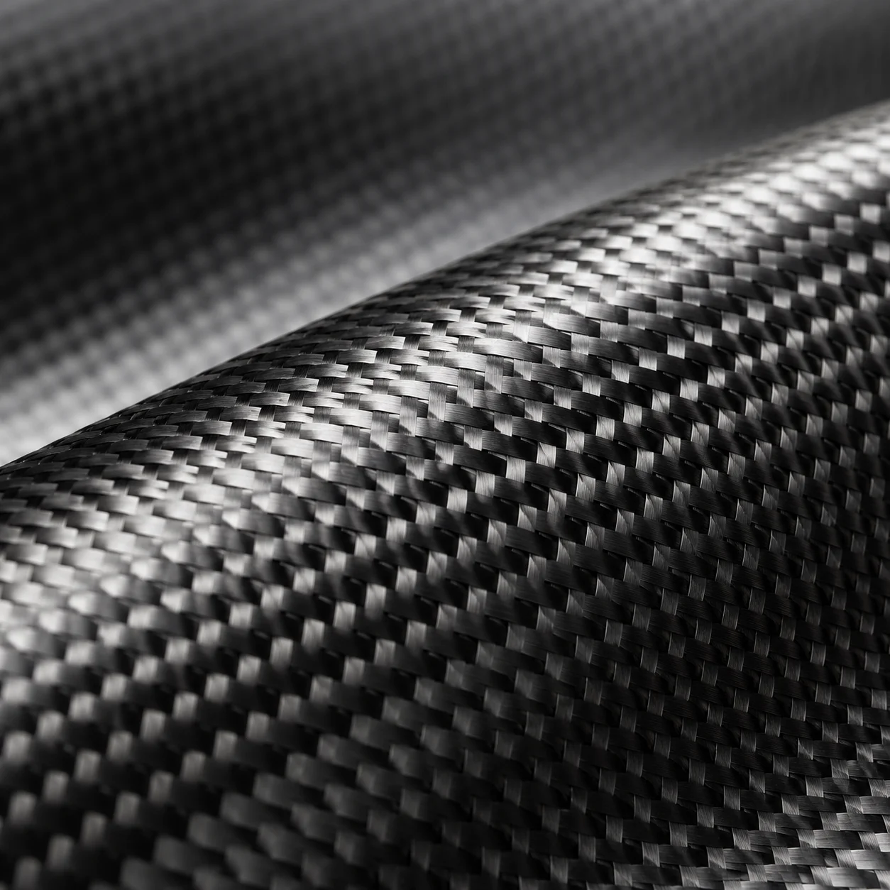
POLYVIA™ Carbon Fiber is a high-strength, high-modulus chopped reinforcement fiber for concrete, cementitious materials and compatible composite systems requiring high mechanical performance, lightweight reinforcement and corrosion resistance.
With tensile strength above 4000 MPa, tensile modulus above 255 GPa and a density of 1.78 ± 0.02 g/cm³, it provides high-performance fiber reinforcement for demanding engineering material systems.
>4000 MPa Tensile Strength · >255 GPa Tensile Modulus · 1.78 ± 0.02 g/cm³ Density
POLYVIA™ Carbon Fiber is a high-strength, high-modulus chopped reinforcement fiber with a carbon content above 90%, combining high mechanical performance with low density and corrosion resistance.
Available in 6, 9, 12, 18 and 24 mm chopped lengths, it is designed for concrete, cementitious materials and compatible composite systems requiring high-performance reinforcement.
Carbon Fiber provides high-strength, high-stiffness distributed reinforcement for compatible cementitious and composite systems where tensile stress, crack development, reinforcement efficiency and corrosion exposure are important design considerations.
High-strength Carbon Fiber can participate in tensile load transfer within the matrix, providing distributed reinforcement where tensile stresses must be effectively managed.
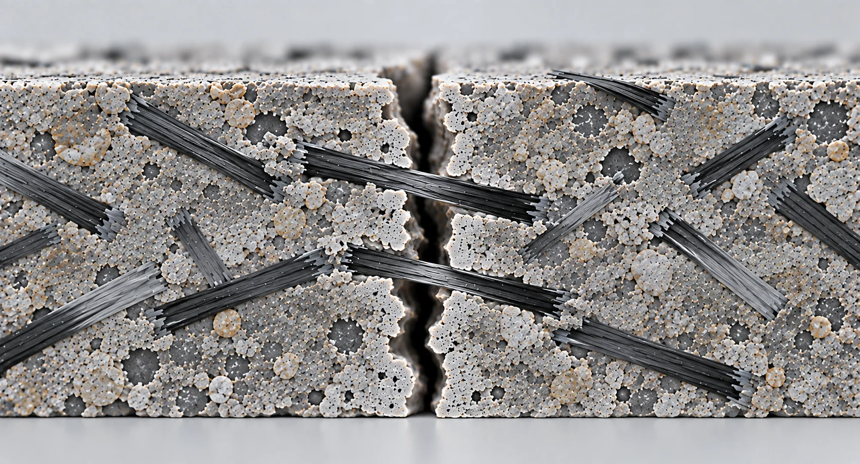
Dispersed Carbon Fibers can intersect developing crack paths and bridge the crack plane, helping transfer tensile stress across localized cracks and restrict further crack opening.
The combination of high strength, high modulus and relatively low density provides a high strength-to-weight profile for systems where reinforcement efficiency is important.
Carbon Fiber does not undergo the electrochemical corrosion associated with steel reinforcement, supporting its use in compatible systems where corrosion resistance is an important material consideration.
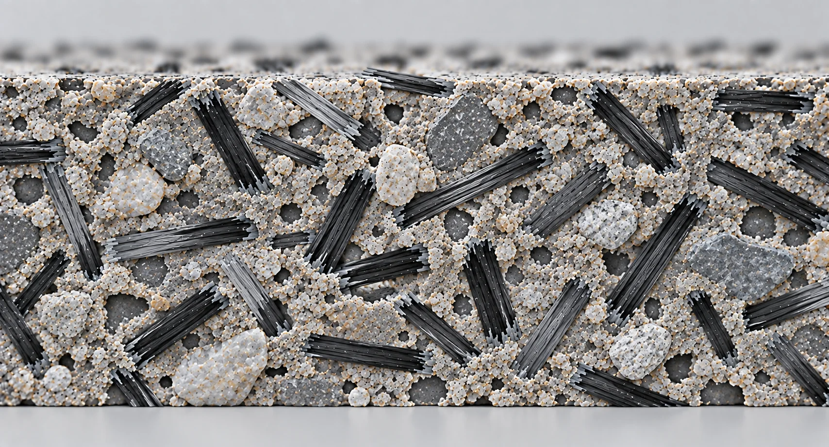
Chopped Carbon Fibers distribute throughout the matrix in multiple orientations, forming discrete reinforcing elements that support tensile stress transfer across the composite.
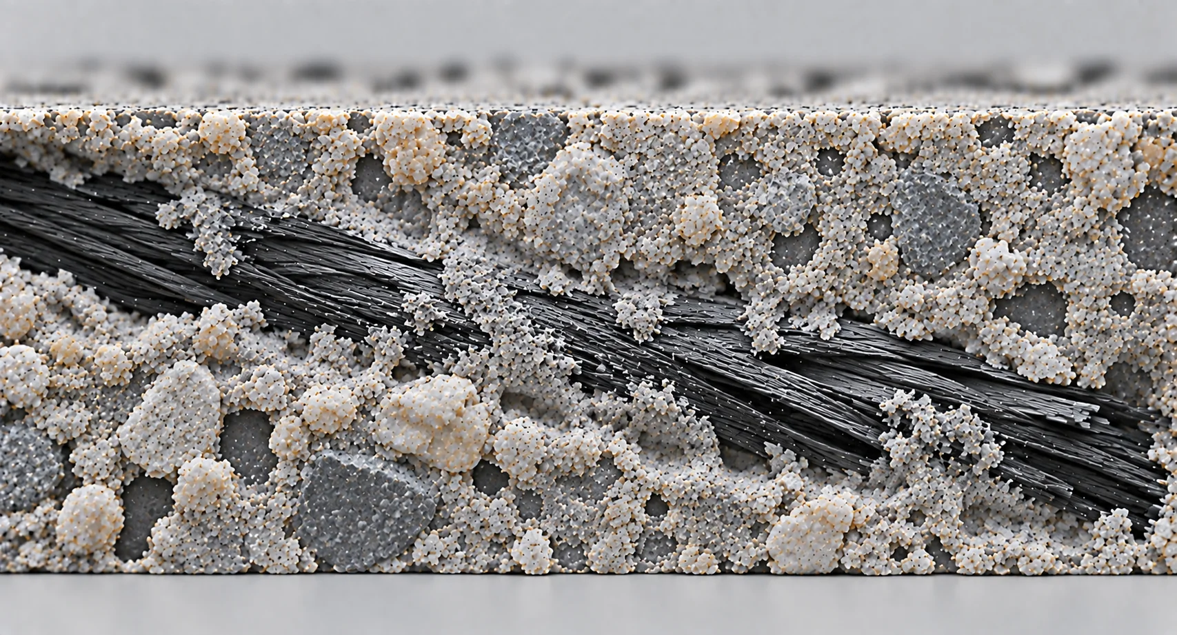
Stress is transferred between the matrix and embedded Carbon Fibers through the fiber–matrix interface, enabling effective tensile load transfer within the composite.
Carbon Fibers intersecting developing cracks can bridge the crack plane, helping transfer tensile stress and restrain further crack opening and propagation.
High-modulus Carbon Fibers help transfer load away from localized stressed or cracked regions, supporting stress redistribution and post-cracking load transfer.
Fiber Distribution → Fiber–Matrix Interaction → Crack Bridging → Stress Redistribution
Chopped Carbon Fiber can reinforce compatible high-performance concrete systems, supporting tensile stress transfer, crack control and distributed reinforcement within the cementitious matrix.
Carbon Fiber can reinforce engineered cementitious composites requiring high stiffness, tensile reinforcement and crack bridging for demanding material-performance requirements.
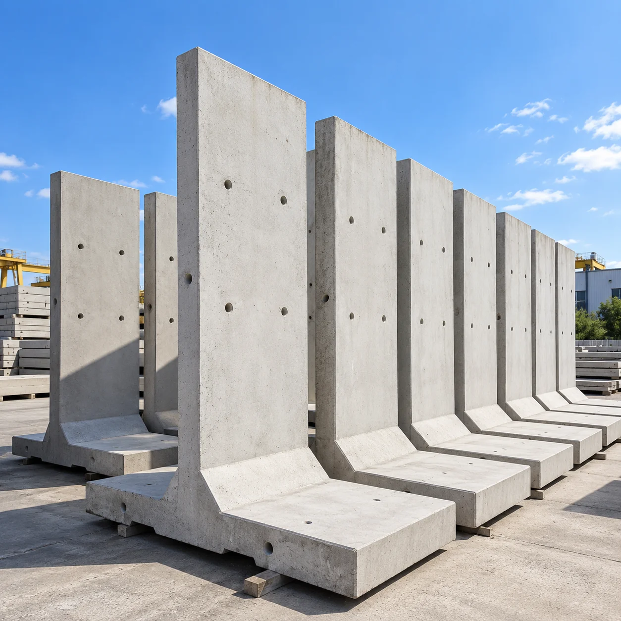
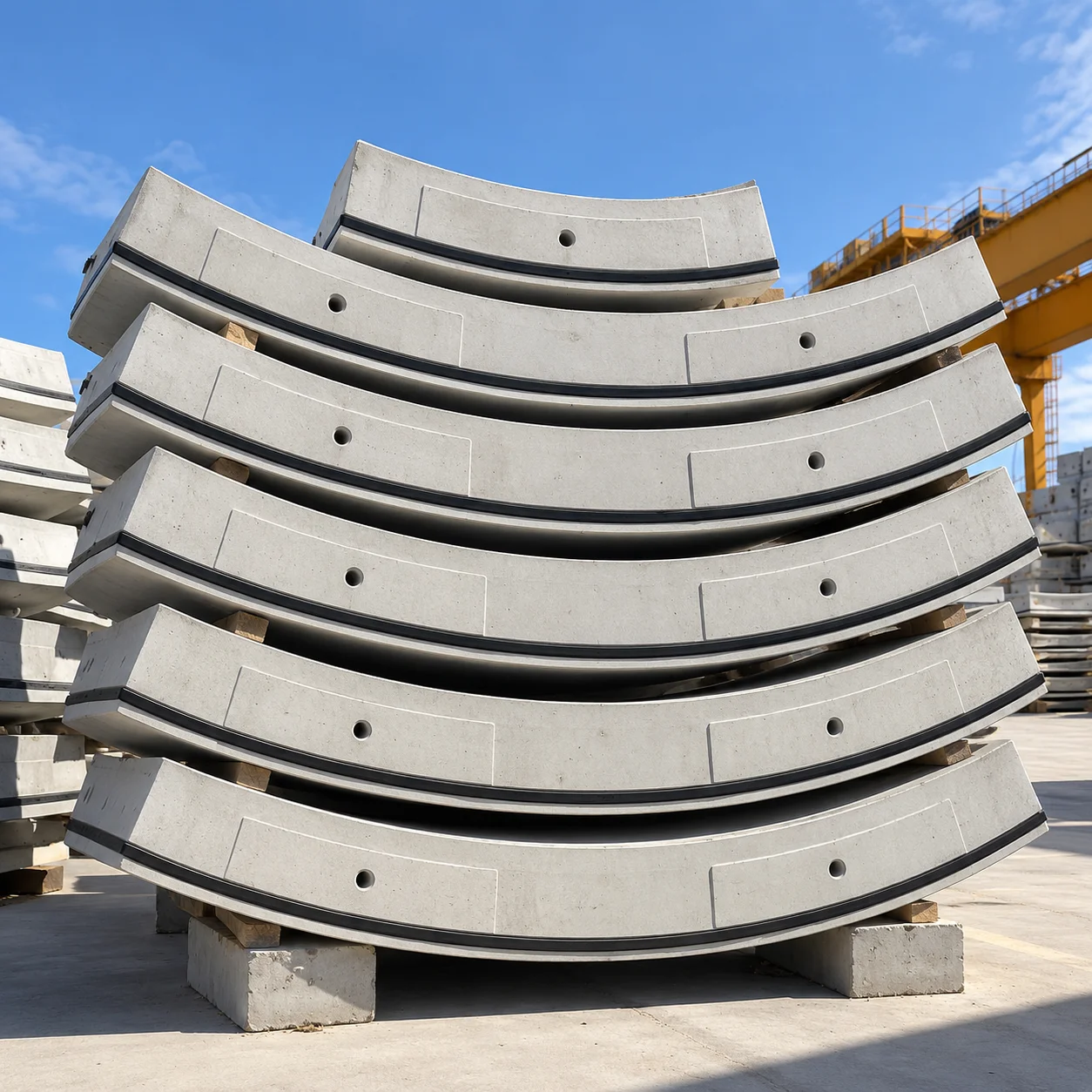
Chopped Carbon Fiber can be incorporated into compatible precast concrete components requiring distributed reinforcement, crack control and corrosion-resistant fiber reinforcement.
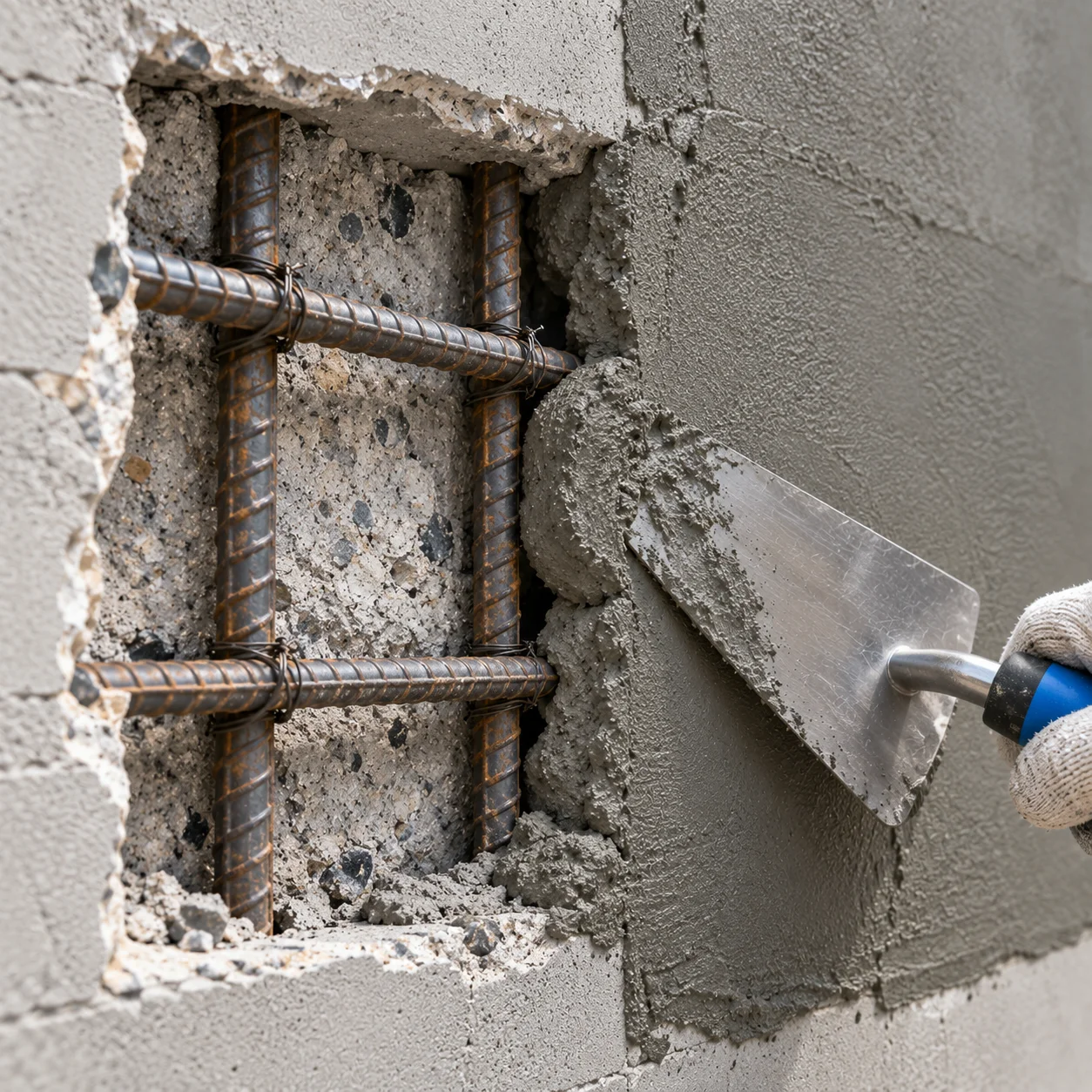
Carbon Fiber can reinforce compatible cementitious repair materials where high mechanical performance, crack control and distributed fiber reinforcement are important design requirements.
Chopped Carbon Fiber can reinforce compatible thermoplastic matrices, supporting higher stiffness, mechanical performance and lightweight reinforcement in engineered composite materials.
Chopped Carbon Fiber can reinforce compatible thermosetting resin systems requiring high strength, high stiffness and lightweight reinforcement for advanced composite applications.
Chopped Carbon Fiber can be incorporated into compatible composite matrices where mechanical reinforcement and electrical conductivity are required within the material system.
Chopped Carbon Fiber can reinforce compatible composite matrices requiring electrical conductivity and mechanical reinforcement for specialized functional applications.
Effective Carbon Fiber reinforcement depends not only on fiber strength, but also on how the fiber interacts with the complete material system. Matrix compatibility, fiber dispersion, interface behavior and processing conditions should therefore be considered together.
The matrix should provide suitable rheology and processing characteristics for effective fiber incorporation. Changes in binder composition, viscosity or other formulation parameters can influence dispersion and final composite performance.
Uniform dispersion is critical to effective reinforcement. Fiber length, dosage and matrix rheology should be balanced with the mixing process to minimize fiber agglomeration and uneven distribution.
The fiber–matrix interface influences how effectively stress is transferred between the matrix and Carbon Fiber. Fiber surface characteristics, matrix chemistry and interfacial bonding should therefore be considered when optimizing the composite system.
Mixing sequence, time and equipment should be matched to the fiber specification, dosage and matrix characteristics. Higher fiber contents or more demanding formulations may require additional dispersion control.
| Property | Specification |
|---|---|
| Density | 1.78 ± 0.02 g/cm³ |
| Carbon Content | >90% |
| Fiber Length | 6 / 9 / 12 / 18 / 24 mm or customized |
| Equivalent Diameter | 5–10 μm |
| Tensile Strength | >4000 MPa |
| Tensile Modulus | >255 GPa |
| Elongation at Break | ≥1.3% |
Uniform fiber dispersion is essential when incorporating Carbon Fiber into cementitious materials. The mixing method should be selected according to the fiber dosage, formulation and processing conditions.
For lower dosages, add Carbon Fiber with the dry components and mix sufficiently before adding water.
Carbon Fiber + Dry Components → Dry Mixing → Add Water → Final Mixing
For higher dosages, pre-disperse Carbon Fiber in a suitable quantity of water before introducing it into the mixture.
Carbon Fiber + Water → Pre-Dispersion → Add to Mix → Final Mixing
Final dosage and mixing conditions should be verified according to fiber length, formulation, dispersion behavior, mixing equipment and required performance.
Product specifications, physical properties and technical data.
Download ↓Product safety, handling and storage information.
Download ↓Batch-specific quality parameters and inspection data.
Request COA ↓Guidance for fiber selection, dosage, dispersion and mixing.
Download ↓Chopped Carbon Fiber is a short-length, high-strength and high-modulus reinforcement fiber. POLYVIA™ Carbon Fiber has tensile strength above 4000 MPa, tensile modulus above 255 GPa and density of 1.78 ± 0.02 g/cm³.
POLYVIA™ Carbon Fiber is available in 6, 9, 12, 18 and 24 mm chopped lengths with an equivalent diameter of 5–10 μm. Customized lengths are also available according to application requirements.
Yes. Chopped Carbon Fiber can be incorporated into compatible concrete and cementitious matrices as distributed reinforcement. Final performance depends on fiber length, dosage, dispersion, matrix design and interface behavior.
For the dry-mix method, the supplied guidance specifies a dosage of typically not more than 0.5%. Final dosage should be verified with the actual formulation and required performance.
For the wet-mix method, the supplied guidance specifies a dosage of typically not more than 2%. The fiber is first dispersed in water before being combined with the other concrete components.
With dry mixing, Carbon Fiber is incorporated with the other concrete components before water addition. With wet mixing, the fiber is first dispersed in water before being introduced into the concrete system
Fiber length should be selected according to the matrix, reinforcement objective, dispersion behavior and processing conditions. There is no universal length suitable for every formulation, so application testing is recommended.
Carbon Fiber should not be treated as a universal one-to-one replacement for steel fiber. The materials differ in density, stiffness, geometry, dosage and fiber–matrix interaction. Any substitution should be validated for the specific concrete system.
Tell us your application, material system and performance requirements. Our technical team can help you evaluate the suitable fiber specification, dosage and mixing method for your formulation. We can also provide guidance on fiber dispersion, matrix compatibility and trial evaluation.