
How to Reduce Surface Voids and Edge Defects in Decorative Precast Concrete
Diagnosing Bugholes, Incomplete Mold Details and Demolding Damage in Architectural Concrete Manufacturing
Surface defects in decorative precast concrete are not always caused by insufficient flowability. Understand how trapped air, mixture rheology, PCE compatibility, mold-release agents, consolidation and demolding procedures influence architectural surface quality—and learn how to identify the root cause through controlled production trials.
IDENTIFY THE DEFECT BEFORE CHANGING THE MIXTURE
Surface Quality Is Part of the Finished Product
Decorative precast concrete cladding must satisfy both material-performance and architectural appearance requirements.
A component may develop adequate compressive strength but remain unacceptable because of exposed surface voids, missing textures, chipped corners or damage during removal from the mold.
This is especially important for mold-cast products reproducing stone textures, ornamental profiles and detailed architectural reliefs.
However, not every visible imperfection represents a structural defect.
An isolated shallow surface void may be acceptable for a heavily textured finish. An open pocket near an anchorage, a crack through a thin section or deep honeycombing may require engineering assessment.
The required appearance should be established through project specifications and approved reference samples.
ACI 309.2R-15 recognizes that completely blemish-free formed concrete is difficult to achieve and does not establish a universal acceptable defect level.
Classify the Defect Correctly
| Defect | Identifying Characteristics | Principal Investigation |
|---|---|---|
| Surface bugholes | Small cavities on the molded surface | Air entrapment, release agent, consolidation |
| Incomplete texture | Missing or poorly reproduced recesses and details | Filling, aggregate size, mold venting |
| Honeycombing | Open, poorly consolidated regions with visible aggregate | Placement, mixture cohesion, consolidation |
| Bleeding or sand streaking | Surface trails or local variations associated with water and fines migration | Water content, stability, mold conditions |
| Edge chipping | Local fracture at corners or projections | Strength, adhesion, removal stresses |
| Surface tearing | Paste or mortar pulled away during release | Mold adhesion, surface integrity, release method |
These categories should be recorded separately. A small bughole and a deep honeycombed region should not be treated as equivalent defects.
Determine When the Defect Forms
Before modifying PCE dosage, identify the likely production stage:
Mixing: Unwanted air behavior or inconsistent dispersion.
Casting: Air entrapment or incomplete filling.
Consolidation: Insufficient air removal or excessive vibration.
Hardening: Bleeding, settlement or early-age defects.
Demolding: Edge fracture, surface tearing or mold adhesion.
Subsequent handling: Chipping, cracking or abrasion.
A defect caused during demolding cannot necessarily be prevented by increasing fresh-mixture flowability.
Engineering Principle: Correct the process responsible for the defect, not merely the visible symptom.
SURFACE BUGHOLES: HOW AIR BECOMES TRAPPED AGAINST THE MOLD
A Flowable Mixture Can Still Produce Bugholes
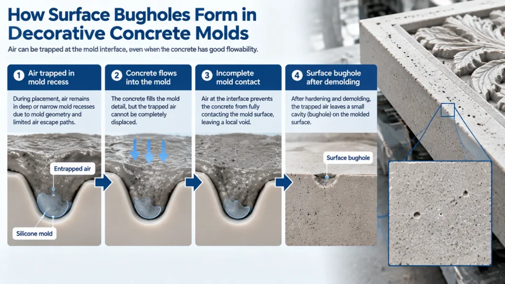
Bugholes occur when fresh concrete fails to establish continuous contact with the forming surface, commonly because air remains trapped at the interface.
Air can enter the mixture during batching, mixing and placement.
As the concrete flows into a mold, this air must escape or move away from the finished surface.
In highly detailed molds, some recesses may create local pockets from which air cannot readily escape.
The result can be a relatively smooth component containing repeated small cavities at specific locations.
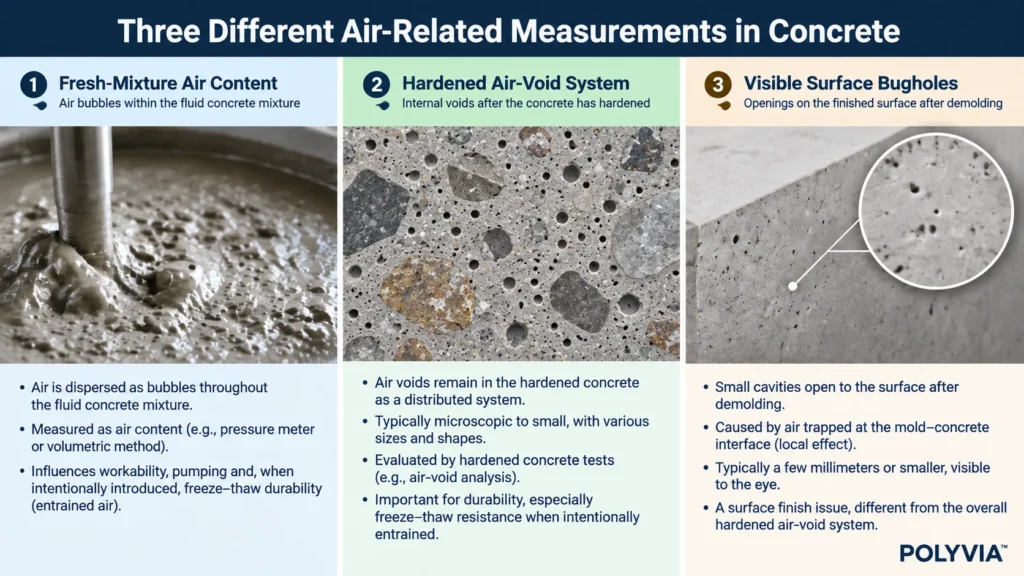
Three Different Air-Related Measurements
A critical distinction is needed between:
Fresh-Mixture Air Content
The amount of air measured within the fresh material using an appropriate testing method.
Hardened Air-Void System
The distribution and characteristics of voids inside hardened concrete, including parameters relevant to freeze-thaw durability.
Visible Surface Bugholes
Cavities exposed on the molded face of the finished component.
These measurements are related but are not interchangeable.
A mixture may have relatively low measured fresh-air content yet still develop localized surface voids because air becomes trapped by the mold geometry.
Conversely, a concrete with a properly designed entrained-air system may show an acceptable architectural surface.
Factors Affecting Bubble Movement
Air movement depends on:
- Mixture yield stress and viscosity.
- Bubble size and stability.
- Particle distribution.
- Placement direction.
- Consolidation method.
- Mold geometry.
- Time available before stiffening.
PCE can change the dispersion and rheology of cementitious particles, while PCE formulation chemistry may also influence bubble behavior.
The review by Xiang and colleagues (2022) summarizes the interactions between PCE, air-entraining systems and bubble evolution.
However, these interactions are formulation-specific. They do not establish that every PCE increases air content or that a particular PCE will eliminate surface voids.
Read the Defect Pattern
| Observation | Investigation Priority |
|---|---|
| Repeated cavities in identical recesses | Mold geometry, local venting or release-agent accumulation |
| Voids concentrated near particular mold edges | Filling direction, local air escape, consolidation |
| Voids distributed across multiple molds from one batch | Mixing, air behavior or mixture consistency |
| Defects increase after changing admixture | Dosage, air behavior, stability and compatibility |
| Defects appear mainly with a new mold | Mold condition, geometry and release practice |
The pattern is evidence for prioritizing an investigation, not proof of causation.
Practical Example: Repeated Voids in One Decorative Recess
Suppose five castings made using the same mold show cavities in the same decorative groove.
The producer should first examine the groove orientation, filling direction, release-agent distribution and possible air escape routes.
If the same batch produces acceptable surfaces in other molds, this strengthens the reason to investigate the specific mold.
Increasing the PCE dosage without checking those conditions may provide little benefit.
MIXTURE RHEOLOGY: BALANCING FILLING ABILITY AND STABILITY
Why Increasing Flow Is Not Always the Answer
Decorative precast concrete must move into complex mold details while maintaining a sufficiently uniform composition.
Two concepts help explain this balance.
Yield Stress describes the resistance to initiating flow under an appropriate rheological model.
Plastic Viscosity describes resistance during flow in models such as the Bingham model.
These properties are not equivalent to a single slump or spread measurement.
An overly stiff mixture may fail to enter narrow details. A highly fluid but unstable mixture may segregate or bleed.
A sticky mixture may also slow bubble migration and make local air release more difficult.
The correct production target is adequate filling ability with acceptable cohesion, stability and air release.
Aggregate Size Can Limit Texture Reproduction
Physical particle obstruction should be considered before increasing admixture dosage.
If aggregate particles cannot pass through a narrow mold feature, additional dispersion will not eliminate the geometric restriction.
For fine decorative details, manufacturers may need to review:
* Aggregate maximum size.
* Fine aggregate grading.
* Paste and mortar volume.
* The dimensions of narrow mold sections.
* Placement and consolidation methods.
Increasing paste volume indiscriminately can introduce additional shrinkage or cost and may alter the finished appearance.
Water Reduction and Stability
A compatible high-range water reducer may enable a lower effective water content at the desired casting consistency.
However, water reduction must be verified by comparing mixtures at defined workability.
Adding PCE to an unchanged mixture and observing greater flow does not, by itself, demonstrate reduced water demand.
Likewise, a lower water-to-binder ratio does not guarantee fewer surface defects if the resulting mixture fills poorly or retains entrapped air.
Evaluate the Actual Casting Window
The mixture should be tested at the time it reaches the mold, not only immediately after mixing.
Relevant observations include:
* Initial consistency.
* Consistency at actual casting time.
* Bleeding.
* Segregation.
* Visible air-related behavior.
* Mold filling completeness.
* Surface defects after demolding.
For fine cementitious systems, mortar-scale test methods may be more suitable than standard concrete tests developed for mixtures containing coarse aggregate.
When Consolidation Needs Adjustment
Insufficient consolidation may leave air pockets and incompletely filled regions.
Excessive or unsuitable vibration may contribute to segregation, bleeding or particle settlement.
The correct consolidation procedure depends on the mixture, component geometry and equipment.
Manufacturers should not assume that longer vibration always improves surface quality.
For highly detailed flexible molds, representative trials should establish how vibration intensity, duration and mold support affect both filling and finished texture.
MOLD PREPARATION, RELEASE AGENTS AND AIR ESCAPE
Mold Conditions Can Dominate Surface Appearance
In decorative concrete production, the forming surface directly determines the visible finish.
Mold preparation should therefore be treated as a controlled manufacturing operation.
Important variables include:
* Mold cleanliness.
* Surface wear or damage.
* Mold orientation.
* Release-agent chemistry.
* Application consistency.
* Temperature exposure.
* Venting and air-trap geometry.
Why Excessive Release Agent Can Be Harmful
A release agent is intended to reduce adhesion between the concrete and mold.
Applying excessive material may create local accumulations, especially in recessed details.
These accumulations can interfere with surface contact and contribute to cavities, staining or nonuniform appearance.
The appropriate release agent and application method must be compatible with the specific mold material.
A process suitable for rigid steel molds should not automatically be transferred to silicone molds.
Silicone Mold Considerations
Silicone molds offer flexibility and can reproduce detailed relief patterns.
However, different silicone formulations have different properties and temperature limitations.
For heated-chamber production, verify:
* The mold supplier's allowable operating conditions.
* Release-agent compatibility.
* Stability during repeated heating cycles.
* Cleaning requirements.
* Dimensional and mechanical behavior during removal.
PCE is added to the cementitious mixture; it is not a mold-release agent.
Neither PCE compatibility nor silicone-mold compatibility should be assumed solely from the product category.
Designing a More Reliable Filling Procedure
Where air is repeatedly trapped in deep features, evaluate whether the mold can be filled in a way that displaces air progressively.
Possible interventions include changing the filling point, placement direction, consolidation procedure or venting arrangement.
These modifications must suit the real mold design.
A generic venting arrangement should not be prescribed without examining the geometry, product thickness and finished-face requirements.
A Controlled Mold Comparison
A simple diagnostic experiment can isolate a mold-related problem.
Use one sufficiently homogeneous concrete batch to produce comparable components using:
* The existing mold preparation.
* A separately defined alternative release-agent application.
* The same filling and consolidation procedure.
Record defects by location after demolding.
Where practical, repeat the comparison and alternate the trial order to reduce the effects of casting time and loss of workability.
If an improvement is consistent, investigate whether it results from release-agent amount, application uniformity or another controlled difference.
PCE AND DEFOAMER SELECTION: CONTROL AIR WITHOUT COMPROMISING PERFORMANCE
Different PCE Formulations Can Behave Differently
PCE superplasticizers are selected primarily for their dispersing and water-reducing performance.
However, their molecular structure and formulated ingredients may influence air-related behavior.
Two PCE products providing similar initial flow can differ in:
Dosage efficiency.
Air behavior.
Mixture stability.
Workability retention.
Setting characteristics.
Compatibility with other admixtures.
For decorative precast manufacturing, these differences justify comparing finished castings—not only laboratory flow values.
POLYVIA Product Selection
POLYVIA™ HWR50 and HWR40 can be considered as high-water-reduction liquid candidates where controlled water demand and casting consistency are priorities.
The appropriate grade and dosage must be confirmed using the actual cementitious system.
A product should not be described as low-air-entraining or anti-bughole unless its performance has been demonstrated under relevant conditions.
When Is a Defoamer Appropriate?
A defoamer may be useful when testing shows that undesirable mixture air or foam stability contributes materially to the defects.
It may be less effective where the primary problem is air trapped by mold geometry or unsuitable release-agent application.
Before introducing a defoamer, establish whether the defect is related to:
- Excessive mixture air.
- Stable bubbles that are difficult to remove.
- Local air traps in the mold.
- Insufficient filling or consolidation.
- Mold-release conditions.
These problems require different solutions.
Protect Durability-Related Air Requirements
Exterior concrete may require an appropriate air-void system for freeze-thaw durability, depending on its exposure and governing specification.
ASTM C457/C457M provides procedures for assessing air-void characteristics in hardened concrete.
A defoamer that reduces unwanted air could also alter an intentionally entrained air system.
Therefore, reducing fresh-concrete air content should not automatically be treated as an improvement.
Where freeze-thaw exposure is relevant, both the specified durability properties and appearance requirements must be satisfied.
Recommended PCE–Defoamer Screening
| Trial | PCE System | Defoamer | Purpose |
|---|---|---|---|
| R0 | Existing | Existing or none | Establish baseline |
| R1 | Candidate PCE | Same as R0 | Compare PCE-related behavior |
| R2 | Selected PCE | Candidate defoamer | Evaluate defoamer effect |
| R3 | Selected combination | Verified trial dosage | Confirm reproducibility |
This is a proposed experimental structure, not a tested POLYVIA formulation.
The trial should record product-as-supplied dosages, relevant solids information, effective water content, mixing procedure and compatibility observations.
Where practical, perform comparisons at both fixed water content and comparable casting consistency.
Evaluate More Than Air Content
Record:
- Fresh-mixture consistency.
- Applicable air-content measurement.
- Bleeding and segregation.
- Finished surface voids.
- Setting and early strength.
- Required hardened properties.
- Durability-related air-void characteristics where applicable.
A successful defoamer trial is one that improves the defined surface problem without compromising other required properties.
EDGE CHIPPING AND SURFACE TEARING DURING DEMOLDING
These Defects Are Not the Same as Casting Bugholes
A cavity formed during casting and a piece of concrete broken away during demolding may appear superficially similar.
Their causes are different.
Surface tearing can occur when the bond or adhesion at the mold–concrete interface exceeds the local resistance of the surface material.
Edge chipping can result from concentrated tensile or bending stresses during removal or handling.
These mechanisms deserve separate inspection categories.
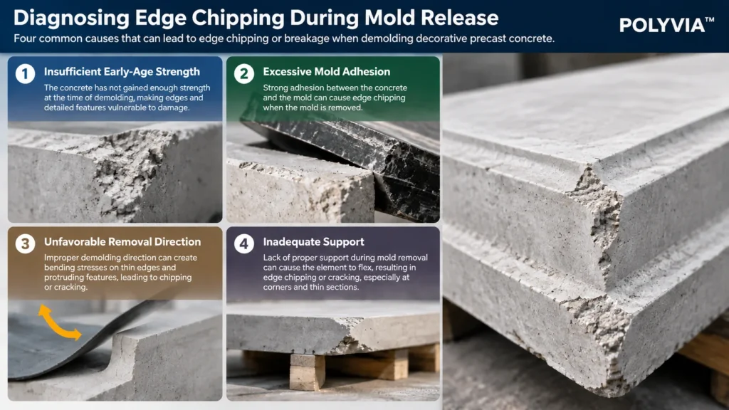
Four Important Causes
Insufficient Early-Age Strength
The concrete may not have developed adequate resistance at the proposed demolding age.
Excessive Adhesion
The mold-release system may be unsuitable or inconsistently applied.
Unfavorable Removal Direction
Peeling a flexible mold can apply bending forces to thin projections and corners.
Inadequate Support
A component may crack or chip under its own weight or under handling loads if not properly supported.
Practical Diagnostic Difference
If the component remains generally soft, evaluate its actual-age strength and curing history.
If the component is otherwise sound but identical corners break repeatedly, investigate local geometry, mold adhesion and removal technique.
Do not automatically increase the accelerator dosage or curing temperature.
Protecting Detailed Features
Depending on the component, manufacturers may evaluate:
A controlled peeling sequence.
1. Better support beneath projecting sections.
2. Alternative mold orientation.
3. Compatible release agents.
4. Improved release access.
5. A verified demolding-strength criterion.
The procedure should be qualified with actual production molds.
Where façade components perform structural or safety-related functions, engineering requirements take precedence over production speed.
Repairs and Acceptance
Minor cosmetic repairs may be permitted under an approved procedure.
However, structural cracks, anchorage damage or deep honeycombing must not be treated as purely cosmetic defects without appropriate assessment.
Architectural repairs should also meet the specified appearance, adhesion and durability requirements.
Preventing recurring defects is preferable to relying on routine patching.
A ROOT-CAUSE TROUBLESHOOTING SYSTEM FOR PRECAST FACTORIES
Diagnose Before Optimizing
A meaningful troubleshooting process begins with controlled observations, not simultaneous changes to water, PCE, release agent and vibration.
Use a structured investigation.
| Production Symptom | First Investigation | Next Controlled Trial |
|---|---|---|
| Repeated bugholes in one recess | Mold geometry and local air escape | Filling direction or venting |
| Surface-wide small voids | Mixing, air behavior and consolidation | PCE/air-control or consolidation comparison |
| Incomplete detailed texture | Particle size, rheology and placement | Aggregate or consistency optimization |
| Bleeding and streaking | Water content and mixture stability | Water/PCE/fines evaluation |
| Surface tearing | Release agent and surface strength | Controlled release-method comparison |
| Corner chipping | Demolding strength and local stresses | Strength or handling verification |
| Defects only after changing PCE | Dosage, air behavior, rheology and compatibility | Old-versus-new PCE comparison |
Case 1 — Bugholes Only in Deep Silicone Mold Features
Use the same formulation initially.
Check local geometry, filling direction, release-agent accumulation and air escape.
A defect that repeats in the same location may be better corrected through mold or placement improvements than through a new admixture.
Case 2 — Bughole Frequency Increases After a PCE Change
Review whether the replacement PCE was dosed on a comparable basis.
A 40% solids liquid and a 50% solids liquid cannot automatically be exchanged at equal product mass.
Furthermore, equal solids content does not guarantee equivalent polymer activity or air behavior.
A controlled comparison should document both product dosage and casting consistency.
Case 3 — Surface Quality Improves but Strength Falls
The improvement may have resulted from increased water, altered air behavior or another formulation change.
Review effective water content, air-related measurements, consolidation and strength results.
A smoother appearance does not justify accepting a mechanically inferior product.
Case 4 — Laboratory Samples Are Acceptable but Factory Components Are Not
Investigate scale-dependent differences:
1. Mixer energy and mixing duration.
2. Time between mixing and casting.
3. Mold size and geometry.
4. Casting height and direction.
5. Consolidation equipment.
6. Mold-release practice.
7. Curing and demolding.
A laboratory specimen is a screening tool, not a complete substitute for production verification.
Use Defect Mapping
Assign identification zones to the mold or finished product.
Record the defect type, location and severity for each inspected component.
Where suitable, photographs taken under consistent conditions can support comparisons.
For repeated casting, compare both defect frequency and whether imperfections recur at fixed locations.
A consistent map can distinguish process-specific patterns from general batch variation.
INDUSTRIAL VALIDATION AND SURFACE QUALITY CONTROL
Establish a Measurable Baseline
Before modifying the process, record the existing formulation and manufacturing method.
Include:
- Cement and aggregate source.
- Pigment system.
- Effective mixing water.
- PCE and other admixtures.
- Mixing sequence.
- Casting time.
- Mold identification and condition.
- Release-agent application.
- Consolidation method.
- Curing and demolding conditions.
Collect representative baseline observations rather than relying on a single favorable or unfavorable casting.
Define Acceptable Appearance
Acceptance should follow the applicable specification or agreed reference sample.
Possible criteria include:
- Number and size of visible surface voids.
- Defect locations.
- Missing texture.
- Edge damage.
- Surface tearing.
- Honeycombing.
- Color or finish variation.
The inspection method should define viewing distance, illumination, inspected area and other relevant conditions.
Do not invent a universal permissible bughole diameter or percentage.
Calculate Defect Incidence Consistently
For component-level inspection:
Surface Defect Incidence (%) = Components With Defined Defects / Total Inspected Components × 100
For example, if 12 of 100 inspected components exceed established defect criteria:
Defect Incidence = 12 / 100 × 100 = 12%
This is an arithmetic illustration, not a measured POLYVIA result.
The metric identifies how many components are affected, but does not describe defect severity.
For detailed architectural surfaces, supplementary measurements may include:
- Defect count per defined surface area.
- Maximum defect dimension.
- Affected surface area.
- Defect severity category.
- Defect distribution by mold zone.
Evaluate the Right Variables
A useful trial record should contain:
| Category | Measurement or Observation |
|---|---|
| Materials | Batch identification, aggregate moisture, admixture dosage |
| Fresh Mixture | Consistency, temperature, bleeding and stability |
| Air Behavior | Suitable fresh-air measurements and qualitative observations |
| Mold | Geometry, cleanliness, release application |
| Placement | Filling direction, time, consolidation |
| Curing | Relevant temperature and time records |
| Demolding | Age, method, observed damage |
| Finished Surface | Defect type, count, location and severity |
| Product Quality | Required strength and durability results |
Use testing methods appropriate to the material.
For example, a fine decorative mortar should not automatically be evaluated with procedures developed for conventional coarse-aggregate concrete.
Separate the Experimental Variables
A practical sequence is:
Stage 1 — Baseline
Record the existing defects without changing the process.
Stage 2 — Mold and Placement
Evaluate justified changes to release-agent application, filling direction or consolidation while keeping the mixture constant.
Stage 3 — Mixture Rheology
If filling or stability is the limitation, screen PCE, effective water content or aggregate grading with controlled comparisons.
Stage 4 — Air Control
If unwanted mixture air is confirmed as a contributing factor, evaluate compatible air-control technology.
Stage 5 — Full-Scale Verification
Repeat the selected solution with actual molds and representative factory conditions.
Quality-Adjusted Production Results
Track more than the number of castings.
Useful indicators include:
First-Pass Acceptance Rate (%) = Components Accepted Without Rework / Total Inspected Components × 100
Rejection Rate (%) = Rejected Components / Total Inspected Components × 100
Rework Rate (%) = Components Requiring Repair / Total Inspected Components × 100
Define the categories so the same component is not inconsistently counted.
Compare trials using consistent inspection rules and representative batch numbers.
An apparent reduction in bugholes is not a meaningful improvement if it is accompanied by increased edge damage, unacceptable strength loss or greater rejection for other reasons.
Validate Hardened Performance
The finished component must still meet the applicable mechanical and durability requirements.
For exterior architectural products, these may involve strength, absorption, weathering, dimensional stability and relevant freeze-thaw performance.
Where air-control admixtures are changed, confirm that durability-related air requirements remain satisfied.
A good-looking surface is not, by itself, evidence of satisfactory hardened performance.
Production Repeatability
A successful trial becomes a reliable manufacturing solution only after repeated confirmation.
Production controls should consider variations in:
- Cement source and batch.
- Sand moisture.
- Ambient temperature.
- Mixing energy.
- Admixture dosing.
- Mold age and cleanliness.
- Release-agent application.
- Consolidation.
- Curing.
- Operator practice.
Record corrective actions and determine whether they remain effective under representative conditions.
Final Engineering Principle
Consistent decorative precast surface quality requires the combined control of:
Mixture Stability → Air Behavior → Mold Preparation → Placement and Consolidation → Curing → Safe Demolding
A suitable PCE can contribute to casting consistency and controlled water demand, but it cannot independently solve every defect.
POLYVIA™ Technical Guidance
POLYVIA™ provides PCE technologies for water reduction and workability control in cementitious applications.
For decorative precast concrete, the appropriate product should be selected using the actual binder system, aggregate grading, mold geometry, casting procedure and surface-quality requirements.
When defects are caused primarily by trapped air in mold recesses, changing the admixture may be less effective than correcting the filling or mold-release procedure.
When unwanted mixture air is demonstrated to be a contributing factor, a compatible defoamer may be evaluated as part of controlled testing.
The final solution should be supported by representative mold trials and repeatable production results rather than by initial flowability alone.
FREQUENTLY ASKED QUESTIONS
1. Why does highly flowable decorative concrete still develop surface bugholes?
High flowability does not guarantee air escape. Air may remain trapped against deep mold recesses or beneath local release-agent accumulations. Examine the defect pattern, filling direction and mold conditions before increasing PCE dosage.
2. Can changing the PCE grade reduce surface voids?
It may, if the current PCE contributes to unsuitable rheology or air behavior. Compare candidate grades under controlled conditions, including actual mold trials. A change in PCE cannot be expected to correct cavities caused mainly by mold geometry.
3. How can a factory tell whether bugholes come from the mold or the mixture?
Compare defect locations across repeated castings and, where possible, different molds using the same batch. Repeated cavities at identical mold positions suggest a local mold or placement issue. Defects affecting multiple molds from a particular batch justify investigation of the mixture and casting process.
4. Will a defoamer eliminate bugholes in silicone-mold concrete?
Not necessarily. Defoamers may reduce certain unwanted bubbles, but they do not automatically remove air trapped by mold geometry or poor placement. Evaluate compatibility, surface results and required durability properties before using one.
5. Should concrete be vibrated longer to obtain a smoother surface?
Not automatically. Inadequate consolidation can leave voids, while excessive or unsuitable vibration may cause segregation or bleeding. Determine the appropriate consolidation procedure through representative trials using the actual mixture and molds.
6. Why do the same decorative corners break during demolding?
Repeated damage at identical corners may indicate local adhesion, unfavorable peeling stresses, inadequate support or insufficient local strength. Evaluate the removal procedure and actual demolding conditions rather than immediately increasing admixture dosage.
7. Is lower concrete air content always better for exterior decorative cladding?
No. Where freeze-thaw durability requires an appropriately entrained air-void system, indiscriminate air reduction may be harmful. Surface bugholes and the internal air-void system must be assessed separately.
8. What should a manufacturer measure to verify that a surface-defect solution works?
Use consistent appearance criteria, record defect type and location, compare repeated batches, and measure relevant fresh and hardened properties. The preferred solution should improve first-pass acceptance without compromising strength, durability or production consistency.
TECHNICAL REFERENCES
[1] American Concrete Institute, ACI Committee 309. (2015). ACI 309.2R-15: Guide to Identification and Control of Visible Surface Effects of Consolidation on Formed Concrete Surfaces.
[2] Xiang, S., Tan, Y., Gao, Y., Jiang, Z., Liu, B., and Zeng, W. (2022). Bubble Evolution under the Action of Polycarboxylate and Air-Entraining Agent and Its Effects on Concrete Properties—A Review. Materials, 15(20), 7053.
DOI: 10.3390/ma15207053
https://doi.org/10.3390/ma15207053
[3] ASTM International. ASTM C457/C457M: Standard Test Method for Microscopical Determination of Parameters of the Air-Void System in Hardened Concrete.
[4] American Concrete Institute, ACI Committee 347. ACI 347.3R: Guide to Formed Concrete Surfaces.
TECHNICAL EVIDENCE STATEMENT
This article combines established concrete surface-quality guidance, published research on PCE and air behavior, and conditional industrial troubleshooting procedures.
All numerical examples are illustrative calculations. No POLYVIA-specific reduction in surface voids, edge damage or rejected components is claimed.
The final admixture and process recommendations must be validated using the manufacturer's actual materials, molds, curing conditions and product specifications.